How do planes land in fog?
Planes land in fog on an ILS radio beam, and on the lowest approaches autoland flies it to the ground. Build it yourself, from one wave to touchdown.
By Joeri Smits, founder of SkyNexus
Planes land in fog by following a radio beam instead of the view. An instrument landing system, or ILS, gives the aircraft a precise line to fly down to the runway, and on the lowest approaches autoland flies that line all the way to the ground. At the bottom of the scale the crew may see little more than a few lights before the wheels touch.
That is the short answer, and it hides a good puzzle. Nothing in the sky marks that line. A few antennas at the airport draw it, and the aircraft reads its position from a small difference between two tones. This post builds that from one radio wave up to an aircraft that lands itself, and each step gives you one thing to play with.
What a pilot needs in fog
Start with the view. Here is a runway on a clear day, from about 100 ft up. Slide the visibility down. When the runway has gone, what would you steer by?
Nothing in that picture helps any more. There is no horizon and no runway, and nothing outside to tell you that you are drifting. Look at what you actually need, though. You do not have to see the runway. You have to know where it is compared with you.
So picture a line in the sky that ends at the runway. Move the aircraft along the approach. What would you need to know at each moment to stay on that line?
From above there is one question: am I left or right of the line? From the side there is one more: am I high or low? Two answers, over and over, all the way down. The rest of this post is about getting those two answers out of thin air.
How does an ILS work?
An ILS is two radio transmitters at the runway. One, the localizer, tells the aircraft whether it is left or right of the line. The other, the glide path, tells it whether it is high or low. Each one moves a needle in the cockpit, and a centred needle means you are on the line. The interesting part is how a radio signal can know where you are, and that starts with one wave.
One radio wave
A radio wave is a rise and fall that repeats as it travels. The frequency says how many repeats go past each second, and 1 MHz is a million a second. All radio waves travel at the speed of light, so the more repeats fit into a second, the shorter each one has to be. Drag the frequency up to see that. The picture is to scale, with an airliner and a person for size. How long is one wave at 110 MHz?
About 2.7 m, or one and a half people. The localizer sends on one of 40 channels between 108.10 and 111.95 MHz, so its waves are all about that long. The play button lets the wave travel, a hundred million times too slowly.
A wave like this says nothing. Think of a lamp that is simply on: you can stare at it for an hour and learn nothing new. Make it brighter and dimmer and it starts to say something.
Radio does the same thing. The wave gets a little taller, then a little shorter, over and over. This is amplitude modulation, or AM, and it is how voices get onto the COM radio in an aircraft. The depth says how much the height changes: at 20 percent the wave swings between 80 and 120 percent of its normal height. The coloured lines below follow the tops and bottoms of the wave. Together they are its outline. Slide the depth up from zero. What happens to them?
The straight lines start to swell and shrink. That movement is the message. The fast wave inside only carries it, so it is called the carrier. A receiver ignores the carrier and follows only the outline.
This plot shows a thirtieth of a second, and the outline swells three times in it. That is 90 times a second, slow enough to hear: send it to a speaker and you get a low hum. That is why it is called a tone.
One note on the drawing. In that thirtieth of a second a real 110 MHz wave goes up and down more than three million times. No screen can show that, so the grey wave here is drawn far too slowly. The outline is the real one.
Two tones
One tone can only say that the station is there. Two tones can be compared, and that is the whole idea of an ILS: more of one tone means you are on one side of the line, more of the other means the other side.
So an ILS puts two tones on the same wave: a low one at 90 Hz and a higher one at 150 Hz. Hz just means times a second. Move the slider from all 150 Hz over to all 90 Hz. How does the outline change?
Alone, 150 Hz makes five bumps here and 90 Hz makes three. In between they add up to one lumpy shape that repeats thirty times a second, and that shape still holds both tones. On the line a localizer gives each one a depth of 20 percent.
A receiver can pull them apart again, the way your ear picks a low note and a high note out of a chord. Picture two filters, each letting through one tone: one for 150 Hz and one for 90 Hz. Then measure how deep each tone is and compare. That is a simplified receiver with perfect filters. Real ones get there in different ways, but they all end up comparing the two. Lean the mix either way, then let go and it springs back. What does the needle do when one tone gets deeper?
With equal tones the needle stands in the middle. Deepen one and the needle leans its way. It does not take much: a difference of 15.5 percentage points puts a localizer needle at the end of its scale.
Why the needle ignores signal strength
Now the question that decides whether any of this can work. Far from the runway the signal is weak, and close in it is strong. Pull the signal strength down and let go. Should the needle care?
The wave nearly disappears and the needle does not move. Depth is a percentage of the carrier, and a percentage does not care about size: 20 percent of a tiny wave is still 20 percent. So in this model the comparison comes out the same near or far, and that is why the needle holds steady as the signal fades, as long as the signal is still strong enough to use.
The plot has no noise in it. In the real world a weak signal drowns in noise, like a voice in a crowded room. So Annex 10, the radio aids standard from ICAO, the UN body for aviation, sets a minimum signal strength.
A comparison also has a trap of its own. If both tones went missing there would be no difference between them, and no difference looks exactly like being on the line. So the sum of the two depths is watched as well, and if the tones go, a flag comes up in the cockpit.
What is a localizer?
The localizer is the part of the ILS that answers left or right. It is a row of antennas beyond the far end of the runway, sending a pattern in which the mix of tones changes as you move off the centreline.
So the signal has to leave the ground different in different directions. Start with the plainest case, one antenna seen from above. Drag time forward. Which way does the wave go?

Everywhere, and the same in every direction. The drawing makes the antenna an ideal point. A real localizer antenna sends mostly forward, but as you move sideways all you would hear is still one wave, a little stronger or weaker. There is no left or right in it.
Two antennas are different. Think of two stones dropped in a pond. Where a crest meets a crest the water rises twice as high. Where a crest meets a trough the two wipe each other out. Radio waves do the same. In this picture bright means a strong signal and dark means the waves cancel. Change the spacing between these two. Where do the dark bands go?

Straight ahead you are equally far from both antennas, so the waves always arrive in step and that direction is always bright. Everywhere else it depends on the spacing: the wider it gets, the more bands fit in. Bright and dark are the raw material of a beam.
Now keep adding antennas in a row across the centreline, each three quarters of a wave from the next. The picture has zoomed out a long way, because a beam needs room to form. Raise the number of antennas. What happens to the bright area in the middle?

With two it fills most of the picture. With fourteen it has closed into a beam. Straight ahead every path is still about the same length. A little to the side the paths from the far ends of the row start to disagree, and the more antennas you line up, the sooner they cancel. This is a simplified array: the outer antennas are fed more weakly, in amounts that are made up.
Two shapes for one needle
A beam still is not enough. A beam is brightest on the line, but brightness alone cannot say which side you are on, and the needle ignores strength anyway. It only cares which tone is deeper. We need one tone stronger on one side of the line, the other stronger on the other side, and both equal on the line itself.
Picture two torches whose beams overlap. One carries 150 Hz and leans a little to the right of the line. The other carries 90 Hz and leans a little to the left. The plot shows how strong each tone is at each angle from straight ahead, as seen when flying towards the antennas. Slide the angle across. What happens exactly on the line?
Right of the line you are deeper into the 150 Hz beam and left of it into the 90 Hz beam. On the line the two cross, so the tones are equal. That is all the needle needs, and it is what reaches the aircraft.
Now look at those two beams again. Most of what is in them is the same. An ILS does not aim two beams. It sends two other signals that add up to them, and each has one job.
The first is the base, called CSB. It carries both tones, equally deep, on one straight beam: the beam you just built, with every antenna in step. On its own it would give equal tones everywhere, so the needle would sit in the middle wherever you were.
The second is the tilt, called SBO. It carries only the two tones, with no carrier, and its 90 Hz is upside down against the 90 Hz in CSB. Like the stones in the pond, where they meet that tone partly cancels. So right of the line SBO adds some 150 Hz and takes the same amount of 90 Hz away. Left of the line it arrives upside down as a whole, and then it does the opposite.
Here are both against the angle. Slide the angle across. What does each one do on the line?
CSB is strongest straight ahead and fades to both sides. SBO is zero straight ahead, goes up on one side and down on the other. Below zero means the same wave, upside down: a crest where it would have had a trough.
SBO comes from the same row of antennas. In this simplified array one half of the row is fed upside down against the other half. Straight ahead the two halves are in balance and cancel exactly. A little to one side that balance is gone, and which half wins depends on the side.
Now add them up with made-up sizes. Say CSB brings 10 of each tone. On the line SBO is 0, so both tones stay at 10. To the right SBO is 2, so 150 Hz gets 12 and 90 Hz gets 8. To the left SBO is minus 2, and the two swap. That gives back the two leaning beams: 150 Hz gets CSB plus SBO, and 90 Hz gets CSB minus SBO.
Why not simply aim two beams? With two beams the line sits wherever they happen to be equally strong, and a small drift in either one moves it. With SBO the line sits where the two halves of the row cancel, and that is fixed by where the antennas stand.
The names come from radio. A tone on a carrier shows up as two faint extra frequencies, just above and just below the carrier, called sidebands. So CSB is carrier plus sidebands, and SBO is sidebands only.
If you keep one thing from this, keep this: CSB is the part that is the same on both sides of the line, and SBO is the part that makes the two sides different.
Depth is a percentage of the carrier, so this plot shows each tone as a share of CSB. Slide the angle away from the line. What does the gap between the tones do?
It grows as you leave the line, with 150 Hz deeper on the right and 90 Hz deeper on the left. The bar between the two dots is what the needle reads. Its proper name is the difference in depth of modulation, or DDM. A DDM of 0.155 is the 15.5 percentage points from earlier, which puts the needle at the end of its scale. Pilots call that full needle.
Two things happen past the edges of this plot. Just outside them, in this simplified array, one tone runs out and the bar stops growing. That does no harm, because the needle is long on its stop by then. Further out CSB passes through zero and the sides swap, so the needle would point the wrong way. That would be a false course. Many real stations cover that area with a second signal called clearance, a few kHz from the first. When both arrive, the receiver follows the stronger one.
The two shapes add up in the air
Now put an aircraft in there, flying up the screen towards the antennas. The rule is that when you face the localizer from the approach end, 150 Hz is on your right hand and 90 Hz on your left. Drag the aircraft across the centreline. What reaches it on each side?
CSB only fades a little as you go across. SBO is zero on the line, grows as you leave it, and turns upside down when you cross to the other side. The rows show only the tones, without the carrier. Added together they give the lumpy shape you met earlier, with one tone deeper than the other, and the needle stands towards the line. Fly to the right of the line and 150 Hz wins, and the needle goes left, which is where the line is. This only works because SBO reaches the aircraft exactly in step with the carrier, and engineers trim that when they set a station up.
The transmitter makes only two signals, CSB and SBO. No single antenna sends what the aircraft hears at its angle. That mix only exists out there, where the two shapes add, so engineers call it space modulation. All the receiver does is read the mix at the spot where the aircraft happens to be.
CSB and SBO also fade with distance in the same way. So the needle depends on your angle and not on how far out you are, which is the signal strength plot again, now in the sky.
Why the needle gets touchy
All of this works by angle from the antennas, so the line in the sky is really a wedge, like the beam of a torch: narrow close by, wide far away. That has a price. Here is the same thing from above, flying to the right, with the sideways direction stretched several times. The antennas stand 3,300 m from the threshold, the point where the landing part of the runway starts. A localizer is normally set up so that full needle is 105 m either side at the threshold. An aircraft flies 80 m right of the line all the way in. Bring it closer with the distance. What happens to the needle?
Far out, full needle is nearly 700 m either side, and 80 m is a small twitch. At the threshold the same 80 m takes the needle most of the way to the stop. The aircraft has not moved any further from the line. The funnel has closed around it, and the needle has become more than six times touchier. Keep that in mind for when an autopilot has to follow it.
What is a glide path?
The glide path is the part of the ILS that answers high or low. It is a second transmitter, beside the runway near the touchdown zone. It sends on its own frequency, around 332 MHz, where one wave is about 0.9 m long, and it uses the same two tones and the same comparison. What changes is the direction: now the mix has to change as you go up and down. Three of the five designs in use let the ground do that work.
Radio bounces off flat ground the way light bounces off a lake. A tree on the shore seems to have a twin hanging below the water, and an antenna does too. So an aircraft up there gets the direct wave, plus a reflected one that seems to come from a second antenna, just as far below the ground as the real one is above it. At these shallow angles the bounce also turns the wave upside down.
That makes two sources again, so the bright and dark bands of the two antennas come back, this time fanning up into the sky. The bright ones are called lobes. Raise the antenna height. Can you make the lowest lobe point 3 degrees up?

The higher the antenna, the more lobes, and the lower the lowest one lies. Along the ground itself it is always dark, because a wave and its upside-down reflection cancel there. About 4.3 m gives the 3 degrees that Annex 10 recommends. That is the sum for a point antenna over perfectly flat ground, and a real site is adjusted on the spot. The ground has become part of the antenna, so snow or flooding can change the result.
One lobe is not a path yet. A bright patch cannot say high or low. We need the same two shapes the localizer had: one that is strong on the line, and one that is zero on it with opposite signs either side. The lower antenna already gives us the first, with its strongest point at 3 degrees.
For the second, put another antenna at twice the height, about 8.6 m. Twice the height gives twice as many lobes, so its first dark gap falls at 3 degrees, right where the lower antenna is strongest. Each lobe is also upside down against the next, so the sign flips across that gap. That is the SBO shape. Send CSB from the lower antenna and SBO from the upper one, and slide the angle up from the ground. What happens to the tones at 3 degrees?
At 3 degrees SBO is zero and the tones are equal. Below that 150 Hz wins and the needle says fly up. Above it 90 Hz wins and the needle says fly down. It works like the localizer turned on its side, with the same comparison of two tones. The main numbers change: each tone is twice as deep, 40 percent instead of 20, and full needle comes at a DDM of 0.175. The path that comes out is about 1.4 degrees thick.
A zero like this is called a null, so this layout is called a null reference glide path. It is the simplest of these designs and wants the most smooth ground. Harder sites use variants such as sideband reference or an M-array, and the idea stays the same.
False glide paths
The lobes keep going, up and up the sky, and that has a strange result. Here is the same ideal model with the DDM, the difference between the tones, drawn as one curve. The dashed lines are full needle: outside them the needle sits on its stop. Pretend you are far too high and slide the angle up past 3 degrees. Where does the needle change its mind?
Up to about 9 degrees it keeps saying fly down, which is correct. Then it comes back through the middle and carries on to fly up. That crossing is a false path. The tones are equal, so it looks like a path, but it is the wrong way round: below it the needle says fly down, and above it fly up. A real path pulls you in. This one pushes you out.
In this layout the cause is that above 6 degrees the CSB lobe is upside down too. A receiver has no way of seeing that, so to the needle the tones have swapped sides. Other layouts flip a different part, at the same angle.
Real signals are messier than this plot, above all near 6 degrees. CSB and SBO both vanish there in the model, and depth is a share of CSB, so the curve shoots up. That tall peak is only a result of the sums. With no signal left, a real receiver would be near its flag. When the Dutch Safety Board and the FAA measured real stations, some had a reversal or a small fly-up area around 6 degrees and others had none. All of them showed fly up above about 9. Annex 10 only asks for the needle to point the right way up to 1.75 times the path angle, 5.25 degrees on a 3 degree path.
On 31 May 2013 a Boeing 737-800 at Eindhoven crossed a 9 degree false path at about 1,060 ft, within 2 km of the runway, and the aircraft locked on to it. There the needle reads backwards. The nose came up at about 3 degrees per second to a maximum of 24.5 degrees, and the stick shaker, which shakes the control column to warn of a stall, followed. The Dutch report says some autopilots, on the 777 and 787 among others, have logic that will not lock on to a reversal like that.
The plot also shows what happens on the way in. Fly level towards the path from below and the first crossing you meet is the real one at 3 degrees. Stay high while closing in and your angle keeps growing. Hold it long enough and you reach the false path from below, with the needle saying fly down the whole way, until it flips. That was Eindhoven. The check in the Boeing training manual is simple: on a 3 degree slope you should be about 300 ft above the runway for every nautical mile from it.
One frequency for two transmitters
Localizer and glide path are two transmitters on two frequencies, but nobody dials two numbers. Each of the 40 ILS channels pairs one localizer frequency with one glide path frequency, so one frequency selects both. Here are four of those pairs, as Annex 10 prints them. Tune the localizer frequency. Can you spot one formula for all four?
There is no single formula. Parts of the table run in neat steps, but it jumps around, so in practice it is a table.
What can go wrong?
All of this is a pattern in the air, and the air is not always empty. The ground makes a useful reflection. Anything else large and metal makes a useless one. Here an aircraft is on final, right on the line. Put an aircraft on the taxiway. What happens to the needle?
It shivers. Part of the signal now reaches you by a second route, and that upsets the mix of tones. The shake is drawn for illustration. How bad it really gets depends on the aircraft, how tall its tail is, which way it faces, and the runway and antennas around it.
So airports keep the space clear. Around the antennas is a critical area, where aircraft and vehicles stay out during ILS operations. Beyond that is a sensitive area, where movement is controlled once the visibility drops. The names vary by country.
When fog comes in, the airport switches to low visibility procedures, typically when the runway visual range, how far you can see along the runway, falls below 550 m or the cloud base below 200 ft. On a good day that protection may be off: in the US, crews are asked to tell the tower if they plan an autoland.
At Munich on 3 November 2011 a Boeing 777 was on an autoland in CAT I weather, the easy end of the ILS scale, with 2,000 m visibility and a cloud base of 300 ft. A departing BAe 146 passed in front of the localizer antenna as the 777 neared the threshold. From about 50 ft the 777 banked left, by up to 3.5 degrees. It touched down about 420 m past the threshold, left the runway twice and stopped on the grass. Summaries of the German report say the disturbance was too brief for the monitors on the ground to register. They put the crew's choice to autoland without that protection first. The autopilot also stayed engaged after touchdown, so it went on following the bent signal.
The ILS watches itself
Those monitors check what the station is actually sending. If the beam moves too far, the monitor has to raise a warning and take the signal off the air, so that the flag in the cockpit comes up. ILS stations come in categories, I to III, and the higher the number the lower they can be used, which is the next section. Here are three, all with the same fault. Push the beam shift up. Which station gives up first?
| Station | Limit | Longest time past it | State |
|---|---|---|---|
| CAT I | 10.5 m | 10 s | On air |
| CAT II | 7.5 m | 5 s | On air |
| CAT III | 6 m | 2 s | On air |
The CAT III station, at 6 m. That is about 6 percent of full needle, and it shuts down anyway. These are the localizer limits in the 2018 edition of Annex 10, at the reference datum, the point 50 ft over the threshold. US values may differ. For CAT I the limit is 10.5 m or 0.015 DDM, whichever is less.
The plot cuts the signal at once. A real station may take the seconds in the table, and then waits about 20 seconds before it tries again. If the monitor itself fails, the guidance has to go as well. For CAT II and III the odds of radiating false guidance in any one landing must be no worse than one in two billion.
What are CAT II and CAT III?
CAT I, CAT II and CAT III are the categories of ILS approach. Each one says how low the crew may go before they need a defined visual reference, usually lights, and how much visibility they need. CAT I stops at 200 ft and CAT II at 100 ft, and that height is the decision height. CAT III goes lower still, down to no decision height at all, and then nothing outside is required before touchdown.
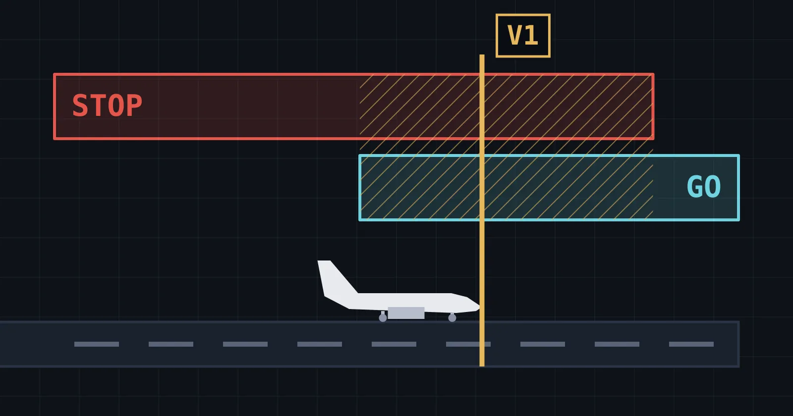
The decision height is where an ILS approach hands the question back to the crew. If they cannot see enough of the lights or the runway by then, they go around, which means climbing away and trying again or diverting. If you have read why V1 exists, this will sound familiar: a decision set up in advance, so that nobody has to work it out at the worst moment.
The fog is reported as runway visual range, or RVR: how far a pilot on the centreline can see the runway markings or lights. Nobody actually stands there looking. Sensors beside the runway measure the fog, and a calculation turns that into a range for an eye about 2.5 m up, reported in steps. From the approach you look down through the fog at a slant, and in deep fog that view is usually shorter than the reported figure.
Bring the RVR down. Each picture is the view from the highest decision height that still allows that fog. What is left to steer by?
CAT I
Decide: 200 ft at lowest
RVR from 550 m
CAT II
Decide: 100 ft at lowest
RVR from 300 m
CAT III
Decide: 50 to 99 ft
RVR from 175 m
CAT III
Decide: Below 50 ft, or none
Rollout: fail-passive
RVR from 125 m
CAT III
Decide: Below 50 ft, or none
Rollout: fail-operational
RVR from 75 m
In this picture, 550 m from 200 ft shows the approach lights long before the runway, and 300 m from 100 ft shows the threshold only just there. At the bottom of the slider you are looking at a few lights just ahead of the nose. That is not much to judge a landing by.
CAT I and II here are the ICAO values. ICAO now has one CAT III: a decision height below 100 ft or none, with an RVR below 300 m or no limit. The CAT III rows are the EU minima from EASA, AMC2 SPA.LVO.100(b), and real minima depend on the aircraft and the approval. CAT IIIA and IIIB are the older subdivisions of that one category. You will still meet them on charts, in simulators and in the FAA AIM. The US has its own numbers, with 300 ft, about 75 m, as the lowest RVR authorized for US operators.
The station has to earn its number. Annex 10 rates a CAT I facility for guidance down to 200 ft, CAT II to 50 ft, and CAT III to and along the runway surface.
A category also takes more than a station. The aircraft has to be certified for it, the airline approved, the crew trained, and the airport has to bring the lights, the RVR sensors and the protected areas. Airbus says that without low visibility procedures in force, even a CAT II or III runway must be treated as CAT I for autoland.
How does autoland work?
Autoland is an autopilot that flies the ILS down to the ground and finishes the job. It follows the localizer and glide path. For the last stretch it measures its own height with a radio altimeter. From about 50 ft it eases off the descent, which is called the flare. It lines the nose up with the runway, and on many systems it steers along the centreline after touchdown, down to taxi speed. The crew supervises. Each of those steps has one idea in it.
Following a needle
Start with the needle. Picture the plainest autopilot you can think of: the further the needle is off, the harder it turns back. How hard is called the gain. This dot starts 200 m to the side of the line, on a beam that keeps one width all the way in. Move the gain up. Which setting would you want to fly behind?
Too low and the dot drifts back so slowly that it is still off the line miles later. In the middle it comes back in a good curve. Too high and it swings through the line, turns back too late, and swings further each time. The aircraft cannot change direction at once, so an eager autopilot is always late. This is a small invented model with one gain, one speed and no limit on bank, plus a little gusty air so that there is always something to correct.
Now remember the funnel. The needle reads an angle, and the same angle covers fewer metres near the antenna. So the same 10 m off the line moves the needle more and more on the way in, which works just like turning the gain up. Keep the good gain from above and let the beam narrow from one width to the real wedge. What happens near the threshold?
Nothing has changed in the autopilot, and the shake comes from the geometry alone. A gain that was calm 6 NM out is too eager at the threshold. We could not confirm from public sources how any given type copes, so this plot just keeps the gain fixed.
What is a radio altimeter?
A radio altimeter measures the height above the ground directly under the aircraft, with its own signal and no help from a station. Autoland needs one because near the ground the glide path runs out of use. It may not be suitable below the lowest decision height, and the path bends close in because the antenna stands off to the side of the runway. So for the last stretch the aircraft measures high or low itself.
Radio altimeters come in two kinds, pulsed and swept. The swept kind works like whistling at a cliff while your whistle slides steadily up. When the echo comes back you have already moved on to a higher note, so the echo sounds lower than what you are whistling now. The further the cliff, the bigger that gap. The radio altimeter does this with a radio signal around 4.3 GHz, pointed at the ground. The echo at 50 ft comes back after a tenth of a millionth of a second. Timing that directly is hard, but a gap between two notes is easy to measure. Change the height. What happens to the gap between the two lines?
The higher you go, the later the echo and the wider the gap. The sweep here is 100 MHz in 10 ms, which is only an example, and real units vary it with height. The picture assumes flat ground and an aircraft that is not moving. Real ground is not flat, so certification looks at cases such as a hilltop or a 6 m sea wall just before the runway. Units for autoland have to be good to 3 ft.
What is a flare?
The flare is the last few seconds of a landing, when the descent is eased off so that the wheels touch gently. On the path the aircraft sinks at 12.4 ft/s, at 140 kt on 3 degrees. That would be a hard arrival: AC 120-28D, the FAA document on low visibility landings, uses 10 ft/s as a touchdown load figure, and that is a limit and not a target.
The trick is an old one: the lower you get, the slower you sink. A Hawker Siddeley paper from the days of the Trident airliner put it as keeping the rate of descent to one-fifth of the height. That alone would never quite reach the ground, because the sink fades away along with the height. So a small extra sink is added and the curve meets the runway at a set rate. Slide the flare height. Where would you start?
Sink = height ÷ 4.8 s + 2 ft/s
Flare length 8.8 s, about 590 m at 130 kt
Start low and the curve is short and sharp. Start high and it floats a long way down the runway. Whatever you pick, this model ends at 2 ft/s, the reference that NASA studies use. It is pure motion, with no pitch, ground effect or wind, and we could not find a published figure for how fast any airliner does this.
From 50 ft the model takes 8.8 seconds to touchdown, about 590 m at 130 kt. That runs long, because the model starts the flare over the threshold, and real wheels are lower there, so real touchdowns come earlier. AC 120-28D sets a box of 60 m to 823 m from the threshold, and wants a touchdown outside it to be about a one in a million event.
Real heights vary by type. On a 747-200 the UK accident investigators describe the FLARE light going green at 50 ft, and on the A320 family the RETARD callout, the cue for the thrust levers to come back to idle, comes at 10 ft with the autopilot engaged. After that it is a question of stopping, and how much runway that takes is what the SkyNexus landing distance calculator works out from your SimBrief plan and the latest METAR.
Landing in a crosswind
So far the air has been still, more or less. In a crosswind an aircraft flies with its nose turned into the wind, like a boat crossing a river, and its track stays on the line. That angle is called the crab. Wheels do not like landing sideways, so the nose has to come round before touchdown. Push the crosswind up and hold it, then let go and it drops back. How far does the nose have to turn?
Crabbed
Nose into the wind, track on the line
Aligned
Just before touchdown where a system aligns, typically wing low
Rollout
Usually the localizer, with the rudder
About 6 degrees at 15 kt, and over 10 at 25 kt. In an incident Airbus uses as a warning, an A340-500 near the limit of that type had 22 kt of crosswind and 9 degrees of drift at 500 ft, and ALIGN, the mode that brings the nose round, only engaged at 30 ft. Where a system aligns before touchdown, AC 120-28D expects it to work like a pilot would, typically wing low into the wind. It also says certification typically demonstrates at least 15 kt of crosswind, and real limits are in each flight manual.
Once on the runway the localizer is usually still the line to follow, now with the rudder, and the rudder fades as the speed falls. Airbus counts an autoland as finished only at taxi speed.
Why autoland needs more than one autopilot
All of this has to keep working when something breaks, so one computer is not enough. Engineers use two words here. Fail-operational means that after any single failure the landing still finishes on the remaining parts. Fail-passive means a failure must not cause a significant change in flight path or attitude, but the landing is not completed automatically, so the crew has to take over.
The A320 family and the 737 have two autopilots. Some larger types have three, as the 747-200 did, and that is the layout drawn here. To be fail-operational a system needs two monitored autopilots, with one left after a failure, or three, with two left to compare. The plot is a teaching picture, and how real channels compare differs by type. Click a box to fail it, then click another. How many can you lose before the landing can no longer finish?
One layout: three autopilots, as on a 747-200.
Fail-operational
These three independent channels agree. If one fails, comparing them shows it, and the landing can finish on the rest.
Two. After the first failure the landing carries on, and what is left is fail-passive. Above a height called the alert height, a failure means going around. One more route exists: a fail-passive autoland backed by a head-up display that a pilot can land with.
Three channels go back a long way. The Trident's Smiths system was built around three, and a Trident made the first automatic landing on a scheduled passenger service, at Heathrow on 10 June 1965. Airbus gives a Caravelle at Orly in January 1969 as the first fully automatic landing with passengers, and accounts differ on what each one counts.
Comparison only helps if the things being compared are independent, and the radio altimeter shows why. In 2011 Airbus wrote that its types other than the A380 carry two and use one at a time, with the other as backup when a failure is detected. The A380 has three and takes the median, the middle value. The 737-800 in the Dutch report had two. Here is the same wrong reading on that flight, on the left, and on an A380, on the right. Flip the switch. What does one bad number do on each side?
The Turkish flight: each on its own radio
All normal
The A380: the middle of three counts
All normal
The 1,000 ft is an example, not the height of the real fault.
On the right the middle value does not move. On the left one number takes the thrust away while the autopilot carries on. That is what happened on 25 February 2009, when a Turkish Airlines 737-800 was on final approach to Schiphol and its left radio altimeter read minus 8 ft, far below the truth, and still reported itself as valid. So nothing switched to the right one.
The autothrottle used the left one, decided the aircraft was flaring and went to idle. The autopilot used the right one and kept holding the glide path. The speed bled away with the nose rising, and nobody noticed until the stick shaker at 460 ft.
The first officer pushed the thrust up at once, but the captain's takeover interrupted that and the autothrottle pulled it back. Full thrust came nine seconds after the shaker, too late. Four crew and five passengers died, according to the Dutch Safety Board.
This was not an autoland. It was a single-channel ILS approach, and the board describes a convergence of several things. But it shows how much trust goes into that one number near the ground.
The whole landing, in fog
That is every piece, and nothing here is new: a localizer and a glide path made of two tones, a radio altimeter for the last stretch, a flare, an align, and the rudder on the runway. Now put them together and take away what the crew would like to have, which is a view. Drag time yourself, or press the button. How low is the aircraft when the windscreen stops being empty?
Following both needles. Nothing outside.
Localizer
Radio altimeter
200 ft
Glide path
In this run the first lights come in at about 130 ft, 15 seconds before touchdown, and the runway at about 75 ft. For the two and a half minutes before that, nothing outside made any difference. The aircraft found a line it could not see and stayed on it, on two comparisons of two tones.
What comes after ILS?
ICAO adopted the ILS as a standard in 1949, and Annex 10 now lists satellite navigation beside it. GBAS takes GPS and adds corrections from a ground station at the airport, and SBAS does a similar job from satellites. EASA assumes that a GBAS landing system behaves much like a conventional ILS, and the questions stay the same: left or right, high or low.
Next time both needles sit centred with nothing outside the window, you know what they are telling you. Two tones are arriving at equal depth, at exactly the place you happen to be.
Questions pilots ask
- How do I autoland in MSFS?
- The exact steps belong to the aircraft you fly, so follow its manual. The shape is the one in this post: tune the ILS, let the autopilot capture both beams in approach mode, and leave it engaged through the flare. A 737-800 needs both autopilots engaged, and the second only engages after APP is selected. Airbus wants at least CAT II on the FMA for an autoland on a CAT I runway.
- How do I find the ILS frequency for a runway?
- It is on the approach chart for that runway. In SkyNexus that is the charts tab. Localizer frequencies run from 108.10 to 111.95 MHz, always with an odd first decimal. You only need this one number, because the glide path frequency is paired with it.
- How do I use approach mode?
- Approach mode tells the autopilot to follow the localizer and the glide path together. The button and its name depend on the aircraft; on a 737-800 it is APP. The glide path is normally met from below, because the first crossing you reach that way is the real one at 3 degrees. The check is height: about 300 ft above the runway for every nautical mile from it.
- What does CAT III mean?
- CAT III is the lowest category of ILS approach. ICAO now has one CAT III: a decision height below 100 ft or none, with an RVR below 300 m or no limit. Real minima depend on the aircraft and the approval. The EU minima, from EASA AMC2 SPA.LVO.100(b), are 175 m for a decision height of 50 to 99 ft, and for below 50 ft or none 125 m with a fail-passive rollout and 75 m with a fail-operational one. CAT IIIA and IIIB are older subdivisions you will still meet on charts, in simulators and in the FAA AIM.
- Why does an ILS need two frequencies?
- Because it is two transmitters drawing two patterns: the localizer on 108.10 to 111.95 MHz and the glide path on about 329 to 335 MHz, paired in a fixed table. Do not mix these up with the two tones, 90 and 150 Hz, which both transmitters send.
- Can planes land in zero visibility?
- Not under any approval we could find. ICAO's CAT III allows for no RVR limit on paper, the old CAT IIIC, but EASA says CAT IIIC has not been used in Europe, where the minimum is 75 m. The lowest RVR authorized for US operators is 300 ft, also about 75 m.
Try SkyNexus EFB
Free, browser-based, runs alongside MSFS 2024, X-Plane or P3D. Import your SimBrief OFP and get the full briefing in under a minute.
Get Started Free